Non-Contact Power Transfer: Rotary motion is transferred from an
input shaft to an output shaft via an electromagnetic connection.
Because there is no physical contact, the system can transfer motion
regardless of the relative angle between the shafts.
Dynamic/Variable Gear Ratios: Unlike traditional magnetic gears
that have fixed physical ratios, electromagnetic gears can alter their
effective number of magnetic poles in real time. This is done by dynamically
changing how the coils are energized, adjusting the magnetic field
strength and sequence.
Full Engagement: In standard mechanical gearing (like spur gears),
power is typically shared by only 1 to 2 teeth at a time during the
meshing cycle. In an electromagnetic gear, the magnetic fields allow
the equivalent of the entire output wheel's "teeth" to be
engaged simultaneously to deliver movement.
In the illustrated diagram, both the input and output wheels feature
alternating magnetic slots positioned opposite electromagnetic coils.
These coils create electromagnetic induction. The input wheel's primary
coil sends an amplified electromagnetic pulse to coils 1 and 4 of
output wheel. Coil B on the input wheel directs pulses, via the amplifier,
to output coils 2 and 5 on the output shaft of the output wheel. Similarly,
Coil C transmits signals through the amplifier to coils 3 and 6 of
the output wheel. This design ensures each input coil energizes two
output coils, with all power amplified by a shared power supply.
This method replaces physical gear teeth with field-modulated electromagnetic
forces. By linking high-resolution front-wheel steering data with
an electronic control unit (ECU), This system creates a frictionless
virtual transmission. Power is transferred across an air gap using
alternating magnetic poles, completely eliminating mechanical contact.
The method and procedure solves the limitations of rigid mechanical
and traditional magnetic gears by providing an electromagnetic transmission
system that decouples the input and output shafts via a flexible electrical
conductor bridge. The system comprises an input assembly and an output
assembly connected exclusively via wire windings. The input
As illustrated conceptually by the system architecture,
the electromagnetic transmission consists of two primary operational
stages linked solely by an electrical conduction pathway, entirely
removing the requirement for physical alignment or intervening mechanical
linkages.
The Generation Stage (Input Assembly)
The input stage utilizes a rotational-to-electrical
transduction mechanism. An input shaft, driven by an external prime
mover (such as an internal combustion engine or an electric motor),
is rigidly fixed to the center of a first rotational wheel. Distributed
circumferentially around this first wheel is a structured array of
magnetic elements, preferably high-energy permanent magnets (e.g.,
Neodymium-Iron-Boron magnets) arranged in an alternating north-south
pole configuration. A stationary stator core supporting a series of
isolated wire windings is positioned to encircle or sit adjacent to
the path of the rotating permanent magnets. Crucially, a precise air
gap is maintained between the rotating magnets and the stationary
windings to prevent physical wear. As the input shaft turns, the moving
magnetic flux cuts through the stationary wire loops. According to
Faraday's Law of Electromagnetic Induction, this action induces an
alternating electromotive force (EMF), manifesting as a stream of
electrical pulses proportional to the rotational speed and magnet
density of the input wheel.2. The Transmission Bridge (Conductor Network)
unlike conventional transmissions that require straight lines-of-sight,
the current generated in the input windings is fed directly into a
flexible wire connection network. This wire network can navigate complex
geometric routing inside an automobile chassis or machine frame.
The Actuation Stage (Output Assembly)
The output stage utilizes an electrical-to-rotational
transduction mechanism located at the terminal end of the wire network.
The electrical pulses enter a second set of stationary wire windings
wrapped around a secondary stator structure. The influx of current
creates a localized, rapidly shifting electromagnetic field. Positioned
across an air gap from these secondary windings is a second rotational
wheel fixed securely to the output shaft. This second wheel features
its own circumferential array of permanent magnets. The dynamic magnetic
flux generated by the secondary windings pushes and pulls against
the permanent magnets of the output wheel, creating continuous rotational
torque about its center axis. Consequently, the output shaft rotates
in synchronized alignment with the input shaft, completely free of
any mechanical rods, chains, or joints.
General assembly of input and output linked by wires
only
3 D view of the assembly with engagement of multiple of output slots
In this optional mode input signal can be fed to another location
of out put wheel by amplifying by the same power supply, so that it
resilt better grip and more power will be aailable in the output shaft.
This is a method and device applicable in power transmission between
the input shaft and the output shaft, eliminating other drives like
shafts, rods, chains, belts, and mechanical joints used in power transmission
from one link to another. Based on this specific utility-eliminating
intermediate hardware like secondary shafts, rods, chains, belts,
and mechanical joints to transmit power directly from an input link
to an output link.
Mechanical drive Vs Electromagnetic drive Comparison
Table
Aspect
Mechanical Shaft Drive
Electro-magnetic Transmission
Power Transfer
Direct torque via drive shaft
Alternator generate electricity send through cables
Efficiency
High at constasnt speed, losses in joints
Slight conversion loss, but felxible control
Maintenance
Requires lubrication and alighnment
Mostly electronic, fewer moving parts
Flexibility
Fixed gear ratio
Variable torque and speed via inverter
Noise and vibration
Mechanical contact causes noise
Smooth, silent operation
Scalability
Limited by shaft length
Easy to extend or modularize
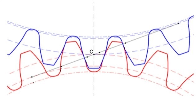
Usually, in mechanical gearing, power is transmitted to the output
through one gear tooth, but in electromagnetic gearing, the entire
output wheel's teeth may be engaged in delivering movement.
1.A straight connection between the input shaft and the output shaft
2.Connection between two shafts in different geometries
3.Belt connection between two shafts
4.Chain connection between two shafts
5.Connection between two shafts using a universal joint
6.Connection between two shafts where the output shaft has to run
at a different speed
7.Connection of the second shaft in which it has to drive in the
opposite direction
8.It includes replacing gearboxes, belt drives, and chain drives
with electromagnetic gears. Reverse can be arranged by placing coils
in reverse positions on output shaft.
This concept illustrates a breakthrough in vehicle power transmission
- replacing the traditional mechanical driveshaft with an electromagnetic
system.
Examples of application:
1. In an I.C. engine, power transmission from crank shaft to cam
shaft
2. Contactless Electromagnetic Gearing & Virtual Differential
System in automobile power transmission
An adaptive steering rod attachment will allows to calibrate rear
wheel actuation to unique steering ratios. This ensures consistent
behavior at turns, with rear wheels responding to the actual road
wheel angle rather than raw steering input.
Rear Wheel Synchronization: If the automobile system directly links
rear wheel actuation to steering input; we need a translation layer
that converts the actual front wheel turning angle (not just steering
wheel rotation) into the correct rear wheel response.
Control Logic should be implimented, instead of mapping rear wheel
movement to steering wheel rotation; maping it to the road wheel angle.
This ensures consistency across different steering ratios.
Practical Implementation
In an electromagnetic gear, the effective number of magnetic poles
can be altered dynamically by changing how the coils are energized.
This electromagnetic differential system replaces heavy mechanical
linkages with intelligent magnetic synchronization. By dynamically
energizing coils, each wheel motor adjusts torque and speed independently,
achieving smooth cornering and adaptive traction. This innovation
merges the precision of electromagnetic gearing with the flexibility
of electronic control - a leap toward lighter, smarter mobility.
Our approach reimagines vehicle power transmission by replacing the
traditional driveshaft with a clean, electromagnetic system. Instead
of mechanical linkages, the IC engine generates electricity through
an alternator, which flows via three phase cables to rear mounted
motors. This innovation - designed in collaboration with Copilot -
highlights how smart electrical coupling can deliver smoother performance,
reduce maintenance, and open the door to scalable, next generation
mobility solutions.
Option 2 - Intelligent magnetic synchronization.
In this option, the rear wheel speed is controlled independently
from the speeds of the left and right front wheels.
This exposed plan shows how Option 2 leverages electromagnetic
synchronization to intelligently manage wheel speeds, replacing traditional
mechanical differentials with a lighter, more flexible system.
This electromagnetic gear system having an intelligent differential
setup, where the rear wheel speed is controlled independently from
the left and right front wheels. In this system magnetic disks are
mounted similar to disk brakes on both front wheels and they sense
rotation by feeding proportional inputs to the coils, allowing each
rear wheel motor to dynamically adjust torque and speed. The Adaptive
Control Rear wheel motors adjust torque and speed separately on rear
wheels, maintaining synchronization between front and rear systems.
This system replaces the heavy mechanical differential with electromagnetic
intelligence. A central disk encoder generates rotation signals, which
our control unit processes to calculate speed and cornering dynamics.
Each rear wheel motor then adjusts independently, synchronizing through
magnetic fields rather than gears. The result is lighter, programmable,
and adaptive - a breakthrough that merges the precision of electromagnetic
gearing with the flexibility of electronic control.
Our electromagnetic differential system replaces heavy mechanical
linkages with intelligent magnetic synchronization. By dynamically
energizing coils, each wheel motor adjusts torque and speed independently,
achieving smooth cornering and adaptive traction. This innovation
merges the precision of electromagnetic gearing with the flexibility
of electronic control - a leap toward lighter, smarter mobility.
This work is licensed under a Creative
Commons Attribution-NoDerivs 3.0 Unported License .
<<<



 ----||---
 >>>
>>>
 The introduced electromagnetic gears can transfer rotary motion from
one shaft to another without a mechanical connection, using an electromagnetic
coupling. This will enable the reduction of heavy metal shafts and
gears, improving the assembly's reliability while reducing the weight.
As a result, electromagnetic gears can transfer motion regardless
of the relative angle. Although they provide a motion ratio similar
to that of traditional gears, they operate without contact.
The introduced electromagnetic gears can transfer rotary motion from
one shaft to another without a mechanical connection, using an electromagnetic
coupling. This will enable the reduction of heavy metal shafts and
gears, improving the assembly's reliability while reducing the weight.
As a result, electromagnetic gears can transfer motion regardless
of the relative angle. Although they provide a motion ratio similar
to that of traditional gears, they operate without contact.