


Sky Metro - The Flying vehicle for public transport
Future vehicles for public transport
These flying commuter busses will be a medium range and short range air vehicles for public transport for commuter transport between two cities areal distant away 30km to 150 Km. The metro will run at the cruise speed of 180Km/ hr. Usually, the landing and take off time will be 4 to 6 minutes. It can land on a flat susface 10 m wide and 20 M long. Driven by electromagnetic thrusters and powered by turboshafts.

They will be equipped with electromagnetic thrusters, powered by turbocharged engines, ensuring sufficient electrical power is supplied to run the electromagnetic thrusters mounted overhead or inside the chassis.
Traditional transportation systems often require navigating obstacles, resulting in wasted energy and time. Recent technological advancements are making previously aspirational modes of travel possible, particularly through the development of vehicles powered by electromagnetic thrusters. In this envisioned future, individuals would travel efficiently and without unnecessary delays, experiencing greater freedom of movement. Enhanced mobility is positioned as a catalyst for a new era in which time is regarded as a valuable asset. Adoption of these innovations has the potential to drive significant societal progress and long-term prosperity.
Sky-Metro VTOL architecture.
Vertical Takeoff and Landing (VTOL) sky metro system for short-to-medium intercity hops (20 km to 200 km)
This is a specialized aerospace-grade modular cargo or multi-mission transport craft
The implementation shifts away from standard grounding
framework definitions toward a high-performance hybrid propulsion
and containerized fuselage assembly.
1. Propulsion & Fuel Integration (The Overhead Arch)
The "overhead arch framework" as an aerodynamic propulsion
mount and fuel system.
Turbo-Shaft Clustering: The arrangement features 4 Turbo-Shaft engines
arrayed symmetrically along the lateral shoulders of the arch. This
provides high-velocity thrust vectors cleared completely from the
lower loading zones.
Central Fuel Reservoir: A large, central Fuel Tank occupies the absolute
apex of the arch layout. This keeps the mass of the changing fuel
weight directly above the longitudinal center of gravity (CG), minimizing
pitch/roll instability as fuel burns down.
Dimensioning Baseline: The critical 6500 mm (6.5m) lateral span across
the inner turboshafts establishes the structural clearance required
for the upper fuselage curvature.
2. Fuselage & Skateboard Platform
The core skateboard platform has evolved into an integrated lower
landing hull and loading ramp bay.
Aerodynamic Upper Shell: The main fuselage features a sloped, low-drag
canopy structure designed to shield cargo or specialized cabin modules
underneath the thermal and acoustic signatures of the overhead engines.
Rear/Front Loading Doors: The base displays a dual-hinged, outward-opening
door configuration. This design provides maximum unhindered clearance
for quick roll-on/roll-off (Ro-Ro) cargo handling, aligning well with
the "skateboard" philosophy.
Multi-Point Ground Support: The underside utilizes a multi-station
landing gear array (visible in both front and side projections), distributing
the structural weight evenly across the platform footprint to avoid
point-loading stress on the lower shell.
Technical Blueprint: Airbus Skateboard Platform (Sky-Commuter
Configuration)
The Airbus Skateboard Platform is optimized into an ultra-wide, short-cabin
50-Passenger Regional Sky-Commuter. Utilizing its massive 9,000 mm
width footprint, the cabin shifts away from traditional narrow-body
layouts to a high-density, ultra-wide lateral matrix, maximizing passenger
throughput for short-range high-frequency routes.
Dimensional & Space Allocations
Total Length: 15,000 mm (15.0 m)
Total Width: 9,000 mm (9.0 m)
Total Footprint Area: 135 m²
Flight Deck & Forward Partition Depth: 3,000 mm
Main Passenger Cabin Depth: 9,500 mm
Aft Service & Pressure Bulkhead Depth: 2,500 mm
3. Key Layout and Structural Observations
Engine Ground Clearance: Raising the turboshaft clusters via the vertical
stanchions completely eliminates foreign object debris (FOD) ingestion
risks during ground ops or unimproved runway takeoffs.
Structural Lever Arms: The vertical support columns holding the engines
and fuel tank. Four heavy turboshafts generate massive dynamic thrust
and vibrational loading, these brackets will experience high moment
forces. These brackets are webbed structural reinforcement at the
base where they interface with the main hull.
Applying the target metric of a 40-passenger short-distance transit
module onto the 15m × 9m skateboard footprint transforms how
we evaluate the spatial layout. By implementing a wide 9-meter cross-section
over a 15-meter length, this design shifts the paradigm toward a high-volume,
ultra-spacious layout with massive interior accommodation flexibility.
The Sky-Metro VTOL architecture.
Now in optimized design configuration:
* The Powerplant & Propulsion: 4
upper-fuselage turboshafts driving a robust grid of 34 distributed
electromagnetic thrusters-using just 6 specialized vectoring units
to handle all steering, yaw, and forward transition flight .
* The High-Capacity Deck: A clean, wingless lifting-body fuselage
built on the 15,000 mm × 9,000 mm skateboard platform, accommodating
144 commuters via a hybrid split (72 seated in a high-density 4-4-4
matrix and 72 standing securely in anchored vertical structural frameworks).
* The Safety Realignments: Zero in-flight refreshments to maximize
space and turnaround efficiency, with the entire 3,500-Liter fuel
capacity safely relocated into an aerodynamically contoured dorsal
spine pod on the roof-completely isolated from the heat-generating
electronics and dual boarding lifts in the bottom platform

Patent App :LK/P/1/22948- Sri lanka
Flying Vehicles in the Foreseen Future

The future of flying Public transport using electromagnetic thrusters is not just a dream,it's a remarkable reality on the horizon. Embrace the possibilities of efficient travel and a new era of transportation! Rotor crafts such as helicopter, Chinook lift and thrust by means of spinning rotors, that require large amount of space to accomadate. Further, these rotor crafts aqurire large space and disturb environmentally by airflow, vibration and noise.
Heavy vehicles in transportation on roads and land
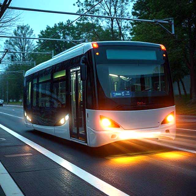
When road vehicles, such as commuter buses and trucks, are equipped with Electromagnetic Thrusters (EMTs), these thrusters can be installed under the vehicle chassis. This design saves space for other equipment, goods, and passengers. One significant advantage of electromagnetic controls is their ability to maneuver vehicles effectively on slippery roads and ice. Instead of relying on traditional brakes to slow down, EMTs can exert force in the opposite direction on the vehicle itself.
Thrusters are poised to revolutionize vehicle propulsion. We firmly assert that forthcoming vehicles will increasingly integrate this technology, and there are compelling reasons for this transition. With their exceptional speed and efficiency, thrusters offer a highly effective means of powering the vehicles of the future.

Local Business Directory, Search Engine Submission & SEO Tools
Style Social Media Buttons
For more details Contact : Leelananda Jayasuriya
E-mail : leel6391@yahool.com